Division 6 NV3340VCOEB Yapım Talimatları - Sayfa 2
Mikrodenetleyiciler Division 6 NV3340VCOEB için çevrimiçi göz atın veya pdf Yapım Talimatları indirin. Division 6 NV3340VCOEB 3 sayfaları.

5
Install Film Capacitor
Install the film capacitor C5, solder the leads, then trim them. Polarity doesn't
matter for this capacitor.
6
Install Trim Pots
Insert R13 and R14 into the PCB and solder into place. Trim the leads.
If you are using the board by itself or creating your own
synth, you can stop here. If you are building a Eurorack module,
keep going!
7
Install Power Connector
Insert P2 into the board, aligning the notch in the connector with the notch
indicated on the silkscreen pattern. Make sure the connector is flat against the
board, then solder it into place. The pins are short enough that they don't
need to be trimmed.
Perform the remaining steps on the control board
CEM3340 VCO Build Instructions
8
Install Right-Angle Header
Insert the right-angle header into the control board as shown, making sure it is
straight. Solder it into place. This header will be used to join the control board
to the main board in a later step.
Flip the board over! From here on out, all the parts go on the other side
9
Install 3.5mm Jacks
Insert the jacks into the PCB, soldering one pin of each as you go to hold it in
place. Check to make sure that they are flat against the board and lined up
with the silkscreen pattern; reheat and reposition if not. Once the jacks are all
in place, test-fit the front panel over the jacks to make sure they all line up with
the panel holes. If everything looks good, go ahead and solder the remaining
pins.
10
Install Pots
Insert the pots into the control board. Place the front panel over the pots and
jacks, thread the appropriate nuts onto the pot and jack bushings, and
finger-tighten them. This ensures that the pots are lined up properly and
mounted at the right height.
Solder the pots into place. Carefully snug all the nuts down using a socket.
11
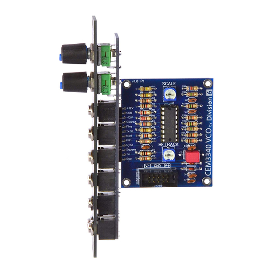
Join the Two Boards Together
Insert the open end of the control board header into the holes on the main
board as shown. Solder one of the pins in the middle, then check to make sure
the two PCBs are at right angles to each other. If an adjustment needs to be
made, heat up the pin you soldered and move the PCBs. When everything
looks good, solder the remaining header pins.
Page 2/3
Continued...
