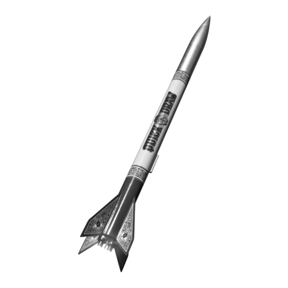
Apogee QUICK DRAW Handbuch - Seite 2
Blättern Sie online oder laden Sie pdf Handbuch für Spielzeug Apogee QUICK DRAW herunter. Apogee QUICK DRAW 12 Seiten.

Assembly Steps
Assembly Steps
1"
Aft Tube Preparation
1. Cut out the fin wrap and wrap it aroundß one of the
Quick Draw
Quick Draw
Tube Marking
Tube Marking
Guide
Guide
Overlap
2. (Optional but highly recommended) Saturate the
Fin
Fixed Mount Assembly and Installation
3. Carefully remove the parts of the fixed mount from
4. Hold ring C (the aft ring) with the label facing toward
Fin
5. Take the two alignment frames and apply wood glue
Fin
6. Rotate the Ring A assembly so that the pins face
Launch Lug
7. Apply wood glue to the center ring (ring B) and the
Fin
Page 2
two 18" BT-80 tubes, taping into place. Mark the lo-
cations of the fins and launch lug. Using an aluminum
angle for alignment, extend the launch lug line the
entire length of the tube and the four fin lines at least
7" from one end of the tube. This will be the aft end of
the rocket.
inside of the aft end of the tube using thin CyA adhe-
sive for a length of approximately 1/4". Hardening the
tube in this way will reduce the potential for damage
to the rocket when swaping removable mounts. Once
the glue has set, lightly sand the inner edge of the
tube to remove any raised lip that may have formed.
the plywood sheet (P/N 12704) using a sharp hobby
knife.
you then – using a needle file – bevel the four edges
to the right of the inner tabs as shown.
generously to all mating surfaces. Insert the the two
alignment frames into ring A (the front ring) from either
side.
you. Ring B is symmetric so, again, direction does not
matter. Apply wood glue to ring B (the center ring) and
install ring B. Clean any glue blobs in the inside or
outside of the assembly with a Q-tip.
alignment pins. Install ring C (which was chamfered
in step 4), taking care that the bevels and label are
facing toward the already assembled parts. Clean
off any glue blobs using a Q-tip as glue in the latch
area will make installation of removable mounts
difficult or impossible. Allow the fixed mount to dry
completely before installation.
Step 1
Step 2
Step 3
B
A
Ring C
Step 4
Step 5
Ring A
Step 6
Ring A
Ring B
Step 7
Label "C" faces
Assembled parts
C
Tab edges
chamfered
