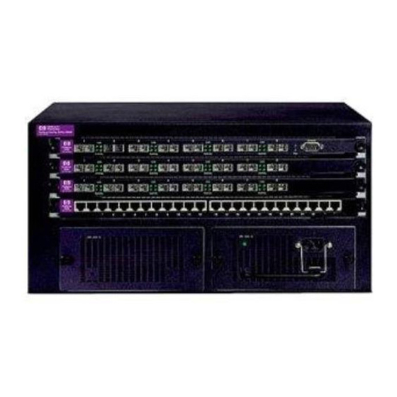
HP ProCurve 1600M Installationshandbuch - Seite 8
Blättern Sie online oder laden Sie pdf Installationshandbuch für Schalter HP ProCurve 1600M herunter. HP ProCurve 1600M 12 Seiten. Redundant power supply
Auch für HP ProCurve 1600M: Spezifikationsblatt (12 seiten), Lies mich zuerst (8 seiten), Handbuch für Rezensenten (27 seiten), Ergänzendes Handbuch (2 seiten), Ergänzendes Handbuch (2 seiten), Installationshandbuch (28 seiten), Installationshandbuch (36 seiten), Installationshandbuch (28 seiten), Handbuch zur Schnelleinrichtung (2 seiten), Handbuch zur Schnelleinrichtung (4 seiten), Benutzerhandbuch (8 seiten), Handbuch Ergänzung (28 seiten), Lies mich zuerst (16 seiten), Montage und Demontage (2 seiten), Handbuch für Planung und Durchführung (40 seiten), Anweisungen zur Demontage des Produkts nach Ablauf der Lebensdauer (2 seiten), Installationshandbuch (46 seiten), Diagnostik-Handbuch (2 seiten), Anweisungen für die Demontage (2 seiten)

