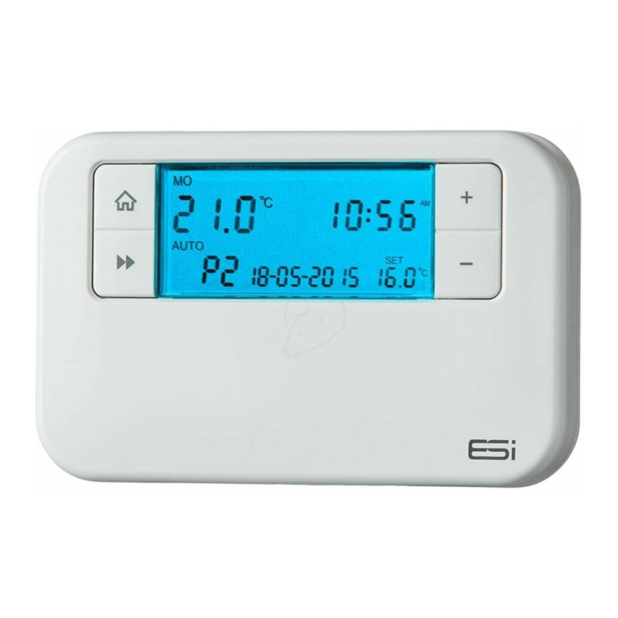
ESI ESRTP4+ Manual de instrucciones de instalación - Página 5
Navegue en línea o descargue pdf Manual de instrucciones de instalación para Termostato ESI ESRTP4+. ESI ESRTP4+ 11 páginas. Programmable room thermostat
También para ESI ESRTP4+: Instrucciones de uso (11 páginas)

- 1. Table of Contents
- 1. 1 Technical Specification
- 1. Programmable Room Thermostat
- 2. 2 Installation Instructions
- 2. Installation Safety Instructions
- 2. General Safety
- 2. Maintenance
- 2. Wiring Diagram
- 3. 3 Technical Settings
- 3. Setting TPI, Delayed & Optimum Start
- 3. Setting Sensitivity/Swing and Calibration
- 3. Opentherm Parameter Settings
- 3. Setting the Landlord Service & Time Events
- 3. Lockout Feature
Warning Notices
2.4
WARNING: Always isolate the AC mains supply before
installing. This product must be fitted by a competent
person, and installation must comply with the guidance
provided in the current editions of BS767 (IEE wiring
regulations) and part "P" of the building regulations.
Wiring Diagram
2.5
ESRTP4+
TM
2XLR(AA)1.5V
Max Load: 1380W
6(2) Amp 230 VAC
OT
OT
For information on wiring to the boiler please
contact your boiler manufacturer directly!
Terminal
Identifier
1
N/C
2
COM
3
N/O
8
0
753677
551329
1
2
3
N/C
N/O
COM
OFF
ON
Description
Normally closed (NC)
Linked Live Feed (230V AC Heating
Applications Only)
Normally open
1.5m
Fitting the Programmable Room Thermostat
2.6
The ideal position to locate the Programmable Room
Thermostat is about 1.5m above floor level, in a location
where the thermostat is accessible, reasonably lit and free
from extremes of temperature and draughts. Do not position
the thermostat near sources of heat, such as radiators, lights,
TV, direct sunlight or on an outside wall
Installation
1. Remove the front cover using a flat screwdriver in the
two holes at the top of the programmer and separate
from back plate.
2. Fix the back plate directly on the wall using suitable
wall plugs and screws.
3. Unscrew the cover that is protecting the live terminals.
Lift the cover to expose the wiring block, taking care to
retain the screw.
4. Complete the connections in accordance with the
wiring diagram (page 8).
5. Replace the thermostat onto the back plate, securing
the bottom of the thermostat first and clicking the
thermostat into place.
9
