HP ProCurve 1600M Manuel d'installation - Page 3

Parcourez en ligne ou téléchargez le pdf Manuel d'installation pour {nom_de_la_catégorie} HP ProCurve 1600M. HP ProCurve 1600M 12 pages. Redundant power supply
Également pour HP ProCurve 1600M : Fiche technique (12 pages), Lisez-moi d'abord (8 pages), Manuel du réviseur (27 pages), Manuel complémentaire (2 pages), Manuel complémentaire (2 pages), Manuel d'installation (28 pages), Manuel d'installation (36 pages), Manuel d'installation (28 pages), Manuel d'installation rapide (2 pages), Manuel d'installation rapide (4 pages), Manuel de l'utilisateur (8 pages), Supplément au manuel (28 pages), Lisez-moi d'abord (16 pages), Installation et retrait (2 pages), Manuel de planification et de mise en œuvre (40 pages), Instructions de démontage du produit en fin de vie (2 pages), Manuel d'installation (46 pages), Manuel de diagnostic (2 pages), Instructions de démontage (2 pages)
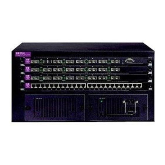
HP ProCurve 1600M Manuel d'installation
HP ProCurve Switch 4000M/8000M
Replacement Fan Tray
The HP ProCurve 4000M and 8000M switches have a replaceable fan tray. The instruc-
tions in this booklet will guide you through the process of replacing the fan tray in
your switch.
Before proceeding, make sure you read the Fan Tray Installation Precautions below.
Included Parts. The following parts should be included in your fan tray replacement
kit:
the Replacement Fan Tray assembly (5092-0373)
HP ProCurve Switch 4000M/8000M Replacement Fan Tray Installation
Guide (5990-3078), this guide
Tools Needed. To complete these procedures you need only a Torx T-10 screwdriver
or a flat bladed screwdriver.
Fan Tray Installation Precautions
Follow these precautions when installing your HP Switch 4000M/8000M Replace-
ment Fan Tray:
Warnings
Make sure that all AC power is disconnected from the switch
before starting the procedures described in this guide. Do not
reconnect the power until the switch is completely reassembled
and cover plates are replaced on any open module slots or power
supply bays.
If your switch is rack mounted, make sure that the rack is not going
to tip over as you complete these procedures. If the switch is
difficult to reach, remove it from the rack or other mounting
location before proceeding.
Cautions
When handling the switch modules, the fan tray, and the fan tray connec-
tor, do not touch the components or edge connectors on any printed
circuit boards, or the pins on any connectors. Otherwise, damage due to
static discharge could occur.
Refer to the installation guides that came with your switch and switch
power supply for precautions on proper handling and installation of the
switch and power supplies. For copies of the installation guides, visit the
HP Procurve web site at http://www.hp.com/go/hpprocurve.
3