- ページ 2
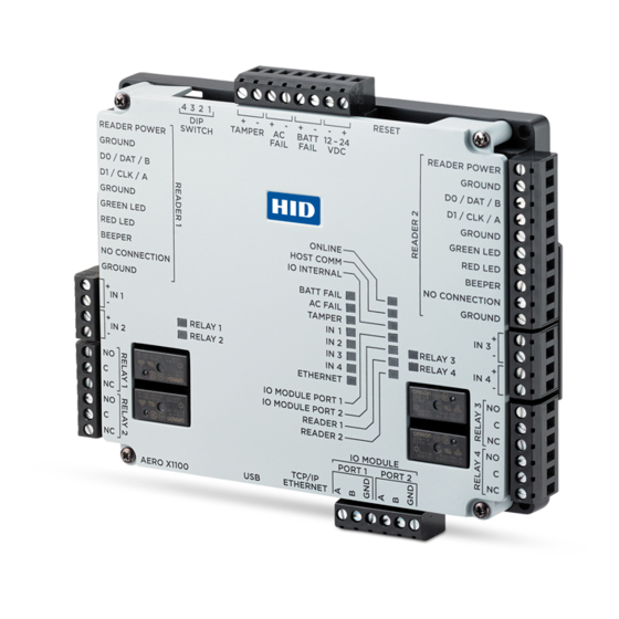
コントローラー HID Aero X1100のPDF インストレーション・マニュアルをオンラインで閲覧またはダウンロードできます。HID Aero X1100 8 ページ。 Intelligent controller

Powering
Trusted Identities
1.
Setting the jumpers
1. If attached, unscrew the four corner casing screws.
2. Remove the X1100 casing to access the battery
jumper and the end of line termination jumpers.
3. Set the battery jumper J4 to ON.
4. Set IO Module Port 1 and 2 end of line termination
jumpers J5 and J9 to IN, only if the X1100 will be the
end of communication bus.
5. Replace the casing and secure with the supplied
four corner casing screws.
Note: The static RAM and the real time clock are
backed up by a lithium battery when input power is
removed. This battery should be replaced annually.
2.
Mounting the X1100
ATTENTION
Observe precautions for handling
ELECTROSTATIC SENSITIVE DEVICES
Always mount the controllers and interface panels
in a secure area.
Mount using the supplied screws 0.138" × 1"
(3.5 mm × 25 mm).
Alternatively mount on a DIN rail using compatible
DIN rail mounting brackets and screws.
See Recommended parts.
Note: The side terminal connectors must be
removed to fit the mounting brackets.
3.
Communication wiring
Connect the X1100 to additional IO modules using
2-wire RS-485 IO Module ports 1 and 2. Use 1-twisted
pair, shielded cable, 120Ω impedance, 24 AWG, 4,000 ft.
(1,219 m) maximum.
Each port can support up to 32 (Aero) or 16 (VertX)
IO modules.
Note: Install RS-485 termination jumpers on the
interface boards at each end of the communication
bus only (see step 1 above). Failure to do so
will compromise the proper operation of the
communication channel.
Network connection
The X1100 controller communicates to the host via the
on-board Ethernet 10-BaseT/100Base-TX port.
2
HID Aero™ X1100 Installation Guide
Battery jumper J4
Termination jumper J9
Termination jumper J5
IO MODULE PORT 1 or IO MODULE PORT 2
To other
devices
on the
bus
Ethernet 10-BaseT/
100-TX port
To other
devices
on the
bus
PLT-04233, Rev. A.3
