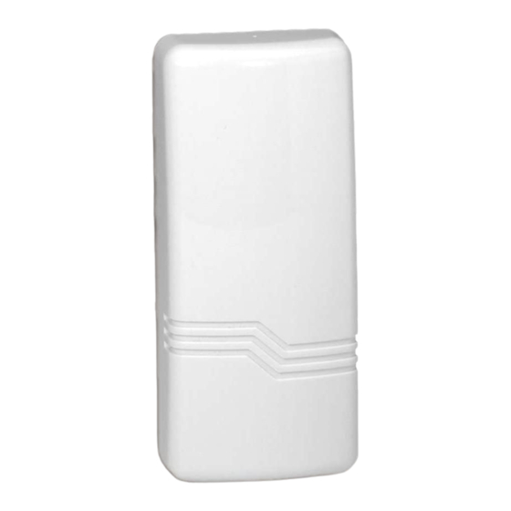
ADEMCO 5817CB 빠른 시작 매뉴얼
{카테고리_이름} ADEMCO 5817CB에 대한 빠른 시작 매뉴얼을 온라인으로 검색하거나 PDF를 다운로드하세요. ADEMCO 5817CB 2 페이지. Wireless commercial /
household transmitter
ADEMCO 5817CB에 대해서도 마찬가지입니다: 설치 지침 (4 페이지), 설치 및 설정 매뉴얼 (2 페이지), 설치 지침 (2 페이지), 설치 및 설정 매뉴얼 (2 페이지)

5817CB
The 5817CB is a universal contact-monitoring transmitter that can be
used with household and commercial fire and burglary-initiating devices
such as door/window contacts, motion and glassbreak detectors,
sprinkler water flow switches, tamper switches, post indicator valves,
manual pull stations and remote duct detectors. Upon activation, it
emits an RF signal to a control panel, sending a burglary or fire alarm
to a central station.
FEATURES:
• The 5817CB has three unique input loops (zones).
• The first loop (primary loop) is supervised and typically used for
high-priority alarm reporting such as commercial fire or burglary.
• The second loop is the built-in, normally closed reed switch used
in conjunction with magnet.
• The third loop is another normally closed household burglary loop.
All three loops may be used.
• A fourth (automatically enrolled) loop contains two tamper switches
to protect the 5817CB.
MOUNTING:
For proper orientation of the unit in relation to its wall mounting plate and the loop wiring, read
entire section before installation. Before mounting the transmitter permanently, conduct Go/No
Go tests to verify adequate signal strength. When a satisfactory location is found, remove the
battery and proceed with installation.
1. Remove the transmitter cover by inserting
the flat blade of a small screwdriver into
the pry-off slot at the bottom end of the
unit (on the right side closest to the
cover's decorative ribs and twisting).
2. Disengage the supplied mounting plate
from the unit by inserting the blade of a
small screwdriver into the mounting plate
release hole (see Diagram 2) and pushing
the locking tab out (see Diagram 1). Slide
the mounting plate downward along the
case back.
Note: For this application, the alignment
guide strip along one edge of the mounting
plate serves no function and may be
broken away, if desired.
3. If concealed wiring is to be used, feed the
wires through the concealed wiring entry
hole on one corner of the plate (surface
wiring is mentioned in step 5 below).
4. Install the mounting plate, with its case-
holding posts pointing up, in the location
selected as described in the installation
instructions. Use the two flat-head screws
supplied. Note: To ensure proper
operation of the unit's back tamper (when it
is separated from the mountain plate), the
screws must be anchored to a wall stud or
other solid wood material.
5. Set the DIP switch (after the control panel
has enrolled the transmitter's input ID's) for
the desired primary loop characteristics, as
described in the table on the following
page.
Wireless
Commercial
Transmitter
