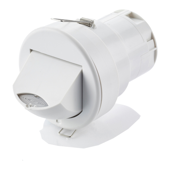
CP Electronics MWS3A-DD-LV 제품 설명서 - 페이지 5
{카테고리_이름} CP Electronics MWS3A-DD-LV에 대한 제품 설명서을 온라인으로 검색하거나 PDF를 다운로드하세요. CP Electronics MWS3A-DD-LV 13 페이지. Ceiling microwave presence detector - dali / dsi 12-24v ac/dc
CP Electronics MWS3A-DD-LV에 대해서도 마찬가지입니다: 설치 매뉴얼 (20 페이지)

Channel 1 (switched output) of the MWS3A-DD-LV
provides a switched low voltage output which can be used
to power a mains load via an auxiliary relay or for other
control purposes. The optional –Gold is used for low
current switching and the optional –OC provides an open
collector output. See diagrams below.
Single channel dimming
Functions: Switches the luminaire with occupancy and maintains illuminance. Dims and switches using optional centre
biased retractive switch (MK K4900 or similar).
Configured to presence detection: Turns on automatically with occupancy. Maintains illuminance. Press and release
down switch to turn off. Press and release up switch to turn back on. Press and hold up switch to dim up, press and hold
down switch to dim down. Turns off after occupancy.
Configured to absence detection: Press and release up switch to turn on. Maintains illuminance. Press and release
down switch to turn off. Press and hold up switch to dim up, press and hold down switch to dim down. Turns off after
occupancy.
6.1 Single channel dimming
Channel mode: Set to "Switch and dim together".
OPTION 2: USING A CENTRE BIASED RETRACTIVE SWITCH TO PROVIDE
Switch mode: Set to "2 position switch together".
INPUT & SWITCH
SWITCHED AND DIMMING OUTPUT (STANDARD CONFIGURATION)
CONNECTIONS
-
DC Supply
11.5VDC - 36VDC
DC Supply
+
11.5VDC - 36VDC
LOAD CONNECTIONS
-PRM-LV
-PRM-LV/GOLD
Load connection
LOAD
6.4 Single channel switching
OPTION 1(B): USING A CENTRE BIASED RETRACTIVE SWITCH TO PROVIDE
ABSENCE DETECTION, WILL ALSO PROVIDE OPTIONAL OVERRIDE OFF.
AC Supply
OR
10VAC - 26.5VAC
-
AC Supply
OR
10VAC - 26.5VAC
+
INTERNAL
RELAY
COM
OUT
+
Channel 2 (dimmable output) of the MWS3A-DD-LV can
be used to control the light output of luminaires that are
fitted with dimming ballasts/transformers.
The ballasts/transformers can be connected in parallel to
Channel 2 (via the DIM– and DIM+ terminals). Refer to the
specification on page 12 for ballast quantities.
The wiring examples below show common methods of
connecting the output channels for a single detector unit.
COM
OUT
COM
DIM-
+
OUT
DIM+
+
SW1/UP
SW2
DOWN
EBDSPIR-DD-LV SENSOR
LOAD CONNECTIONS
-PRM-LV/OC
LOAD
Wiring diagrams
DIMMING
BALLAST
DIMMING LUMINAIRE
(DSI or DALI)
MOMENTARY PUSH TO
MAKE SWITCH
Optional for presence,
mandatory for absence detection
CENTRE BIASED
RETRACTIVE SWITCH
Optional for presence,
mandatory for absence detection
INTERNAL OPEN
COLLECTOR
TRANSISTOR
COM
OUT
+
5
