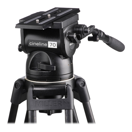
Miller cineline 70 운영자 매뉴얼 - 페이지 11
{카테고리_이름} Miller cineline 70에 대한 운영자 매뉴얼을 온라인으로 검색하거나 PDF를 다운로드하세요. Miller cineline 70 17 페이지. Fluid head

4.4 Using a 3 mm Hex key unlock the LOCK SCREW (fig. 6),
then using a broad flat screw driver turn the ADJUSTING
SCREW (fig. 6) in the direction shown by 1/8 of a turn
and re-check step 4.2, repeat 4.4 if necessary. When
adjusted correctly, the SIDE LOAD LOCK LEVER will be
smooth to operate and require modest effort to lock the
CAMERA PLATE.
4.5 Once the correct adjustment is achieved, remove the
CAMERA PLATE and lock the LOCK SCREW.
Camera Plate
Camera Plate
Camera Plate
11
Turn Adjustment Screw
Counterclockwise to
compensate for a wider
camera plate.
Correct position of Side
Load Lock Lever at the
start of locking action.
Turn Adjustment Screw
Clockwise to compensate
for a narrower camera plate.
Fig. 9
