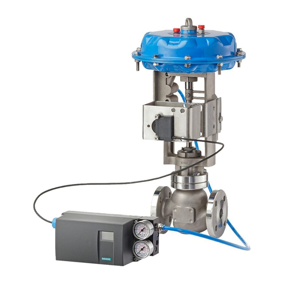
Siemens SIPART PS2 설치 지침 - 페이지 8
{카테고리_이름} Siemens SIPART PS2에 대한 설치 지침을 온라인으로 검색하거나 PDF를 다운로드하세요. Siemens SIPART PS2 11 페이지. Mounting bracket kit
Siemens SIPART PS2에 대해서도 마찬가지입니다: 설치 지침 (4 페이지), 사용 설명서 (28 페이지), 설치 지침 (4 페이지), 하드웨어 설치 매뉴얼 (30 페이지), 기술 설명 (26 페이지), 간결한 사용 설명서 (35 페이지), 키트 설치 지침 (9 페이지)

15900-795
INITIAL PS2 SETUP
Perform the following steps to set the transmission gear ratio switch,
apply instrument air and electrical power, and manipulate the three
setup pushbuttons to initially set up the PS2. Read the cautions on
page 3 before proceeding.
1. Loosen the four captive screws securing the PS2 cover and
remove the cover.
2. Find the specified valve travel and refer to Table 5 for the
transmission gear ratio switch setting: 33 or 90.
3. Refer to Figures 5 and 7 and to the top label on the PS2 to, if
necessary, change the transmission ratio switch position. Use a
small screwdriver to shift the position of the slide switch/bar.
4. Connect tubing from positioner output port, labeled "Y1" on
positioner cover, to actuator inlet.
5. Connect tubing for instrument supply air to positioner supply port
labeled "Pz". Apply air pressure.
!! Do not exceed maximum casing pressure shown on
actuator Warning label.
6. Connect a DC power source to positioner terminals; see Figure 5
for a typical electrical connection label. Electrical connections
vary with positioner model and options. Apply electrical power.
Transmission Gear Switch Settings
FIGURE 5 PS2 Transmission Gear Ratio Switch Location (PS2 Cover Removed)
8
TABLE 5, PS2 Transmission
Gear Ratio Switch Setting
Transmission
Bar
Stroke
Setting
0.71"
33
1.10"
90
1.50"
90
2.28"
90
Use a small
screwdriver to shift
the yellow
transmission gear
switch from 33 to
90.
Shift from 90 to 33
from other side of
PS2.
