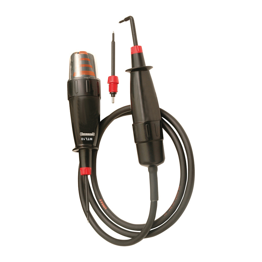
Drummond MTL10 Instruction Manual - Page 3
Browse online or download pdf Instruction Manual for Test Equipment Drummond MTL10. Drummond MTL10 5 pages. Test lamps
Also for Drummond MTL10: Instruction Manual (5 pages), Instruction Manual (20 pages), Instruction Manual (5 pages)

The magnitude of a voltage is indicated by the illumination of LED's
in four separate bands around the top of the instrument body.
The nominal voltage thresholds of the indicator LED bands are 50V,
120V, 230V and 400V and are marked next to the relevant band.
The indicator LED bands will illuminate when the magnitude of
the voltage source is at a value approaching or greater than the
corresponding marked voltage. For example if the voltage source is
55V AC rms then only the 50V indicator LED band will illuminate, if
450V AC rms all four indicator LED bands will illuminate.
Note: The individual LED indications are not to be used for
measuring purposes.
3.3 Operating Duty Ratio
The voltage indicator should be operated (ON) for a maximum
period of 30 seconds. This should be followed by a recovery period
(OFF) of 4 minutes.
The operating duty ratio is 8 to 1, so if the voltage indicator is only
ON for 2 seconds then the OFF period need only be 16 seconds.
3.4 Proving Check
Before each use the voltage indicator should be examined for
damage, cracks, cuts or scratches to the housing, cable and prods.
The cable has black outer and contrasting inner insulation, to allow
damage to the cable to be easily identifi ed. If there is any doubt the
voltage indicator should not be used.
Before and after use, verify the voltage indicator is functioning
correctly with a proving device (PD430 or PD440 is recommended),
or a known good voltage source. Do not use the voltage indicator if
any expected LED's fail to illuminate correctly during proving.
While taking all required safety precautions connect the test prods
across the test points where a voltage difference may be present.
The voltage level of any voltage present between the test points will
be indicated by the illumination of the relevant voltage indicator LED
bands.
3.6 Push Button Switches (MTL20 only)
The purpose of the push button switches on the MTL20 is to provide
additional load to the circuit under test where the presence of
interference (phantom) voltage may be suspected (see section 3.7).
Simultaneous depression of both switches (one on the probe handle
and one on the instrument body) introduces a load of approximately
8.8 k to the circuit being tested.
Note: Interference (phantom) voltages can rise again after the push
buttons are released. If a voltage indication re-appears on the LED
bands while the buttons are not pressed, there may be a hazardous
voltage that must be treated with caution.
3.7 Interference (Phantom) Voltage
It is possible for wiring that is 'dead' to indicate the apparent
presence of voltage at power frequency.
If wiring that is live is running in close proximity to the 'dead' wiring
being tested, there can be capacitive or inductive coupling between
the two, thereby causing interference (phantom) voltage.
Voltage indicators that draw a relatively low current when testing for
hazardous live voltage may not be able to suppress the interference
voltage to a low enough level so as not to indicate the presence of a
hazardous live voltage where there is not one.
The MTL10 & MTL20 will suppress typical levels of interference
voltage as defi ned by the test for interference voltage in the
standard EN 61243-3:2010.
Warning
If the proving device or voltage source exceeds the specifi ed limits
of the voltage indicator the voltage indicator may be damaged and
the operator may be exposed to a shock hazard. Always check the
specifi cation of the proving device or the voltage magnitude of the
voltage source before proceeding with a proving check.
The LED bands that illuminate during proving will depend on the
magnitude of the proving unit output or the voltage source.
For example if the voltage source is 230V AC rms then all LED bands
except the 400V LED band must illuminate. If a PD440 is used then
all LED bands must illuminate.
During this verifi cation emphasis should also be place upon the
fl exing of the voltage indicators cable along its length, and particularly
at the entry points to the hand held elements, to confi rm that the cable
has not been fractured.
If using a PD430 or PD440 for proving, the press button switches
on the MTL20 can also be functionally checked. In this case when
both buttons are pressed simultaneously the 400V LED band will
cease to illuminate, indicating that the added load of the MTL20 has
caused the output voltage of the PD unit to drop, thereby proving the
functionality of the switches and loading circuit.
Any unexpected display should be investigated and the voltage
detector not used until all expected LED's illuminate.
3.5 Testing for the Presence of Hazardous Live Voltage
Warning
Hold the unit and test leads behind the fi nger guards in a manner that
will not obscure the voltage band indication LED's. Never touch the
exposed metal test prods or any part of the instrument forward of the
fi nger guards while applied to hazardous voltages.
7
8
05/12/2013 11:31:07
MTL10 MTL20 instructions rev8.indd 13
Interference voltage that may be of a higher level than 'typical' may
not be suppressed by the MTL10 but should be suppressed by the
MTL20 when the push button switches are pressed to introduce a
higher load.
If there is any doubt as to whether a voltage indication is hazardous
live or interference, then alternative tests should be performed.
9
10
05/12/2013 11:31:07
