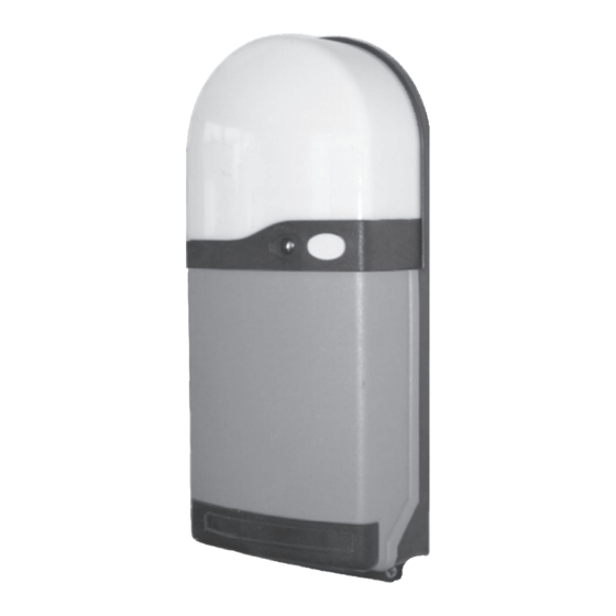
Ansa RS-1 Instrukcja instalacji i obsługi - Strona 10
Przeglądaj online lub pobierz pdf Instrukcja instalacji i obsługi dla Jednostka sterująca Ansa RS-1. Ansa RS-1 12 stron. Ansa roller door remote control unit

- 1. Table of Contents
- 2. General Description
- 3. General Operation
- 4. Multi Channel Keyfobs
- 5. Fitting the RS-1 Control Unit
- 6. Electrical Connections
- 7. Photoelectric Cell Safety System (Optional)
- 8. Light Grid Safety System (Optional)
- 9. Alarm System (Optional)
- 9. Figure 16
- 9. Commissioning
- 9. Adding/Deleting Transmitters & Wireless Access Controls
- 9. Dip Switch Options & Special Settings
- 9. Technical Specifications
10 Adding Transmitters & Wireless Access Controls
Keyfobs supplied are normally preprogrammed . Extra keyfobs or other wireless access control devices are added as follows. Press
the operating button for 5 seconds and release when the red LED indicator goes out. The LED will flash once to confirm Add Mode.
Take the new transmitter to be added and press the button once. The red LED indicator should flash once. Repeat this for every new
transmitter to be added to the system. After the last transmitter has been added either wait 30 seconds or press the operating push
button once to reset to normal operation. The remote control system uses the latest "rolling code" technology. Hand transmitters
supplied are pre-programmed. The receiver can memorise the codes of 15 transmitters. Upgrade memory chips are available for 31
or 62 transmitters by special order.
11 Deleting Transmitters & Wireless Access Controls
It is not possible to selectively delete transmitters and selecting delete mode will erase all transmitters from the system. Switch off the
power supply to the unit and remove the front cover. Turn on Dip switch 5 and re-power the unit. The circuit board mounted yellow
"set radio" LED will illuminate for 5 seconds, all transmitters are now deleted. Switch off the power supply , turn off Dip switch 5 and
re-fit the front cover. Transmitters (and other wireless access controls) can now be reloaded using the "Add Transmitters" procedure.
12 Multi-Door Control
Four types of Transmitters are available, 1, 2, 3 or 4 buttons, therefore up to four doors each fitted with a
be controlled independently using a single transmitter. Simply select the transmitter button you wish to use with a particular door and
programmes the transmitter as per section 10 "Adding Transmitters".
13 Holiday Mode
In some instances it may be helpful to switch off the controls operating the door temporarily without turning off the mains power
supply or erasing transmitter security codes.[For example during holiday periods] To activate this feature simply press and hold the
operating button for approximately 12 seconds and wait until the red indicator LED flashes slowly. To return to normal operation
switch off the power supply to the control unit for five seconds and then switch back on.
14 Fault Diagnostic System
The microprocessor monitors the circuit board , low voltage control wiring, control devices connected to the system and safety
systems and detects possible faults. If a fault is detected the door cannot be operated and the red LED will flash slowly. The power
supply should be switched off until the fault is found and corrected
15 Dip switch options &Special settings
The RS 1 control unit has six onboard Dip switches which control the following features.
15.1
Dip switch1 Warning.
15.2
Dip switch2 Retract.
200mm instead of returning to the fully open position.
15.3
Dip switch 3 Security.
adjustment of screw type motor limit switches Dip switch 3 is normally turned off. Additionally for doors having an externally fitted
manual override system, switching on Dip switch 3 selects a security system. If the manual override system is used to force open the
door, the system will power down the door to the closed position.
Note- When using the security system it is important to accurately set the motor run timer. operate the door
from the fully closed to the fully open position and adjust the run timer so that the circuit board "open" LED goes out five seconds after
the door arrives at the fully open position. See Fig 10
15.4
Dip switch 4 Auto- Close.
function. The time delay begins when the door is fully open and is reset if the photoelectric safety beam or light grid is activated. The
auto-close delay is dependant upon door size and operating speed. Set the motor run timer as described in "security", the
corresponding auto close delay is shown in Fig 10.
Note ; Selecting Auto-close increases the level of automation and to comply with relevant safety standards we
recommend autoclose is only used with doors having the Light Grid System .
15.6
Dip switch 5 Generator Mode / Motor Current Sensing System Off.
using a portable power supply generator and for small doors Dip switch 5 will also switch off the Motor current sensing (anti
entrapment) system.
15.6
Dip switch 6 Decode.
3
4
2
5
1
6
0
Page 9
When switched on, the courtesy light will flash three times before the door moves.
When switched on, selects partial retract. If the photocell or Light grid system is activated, the door retracts
When switched on, extends the motor supply feed for the duration of the motor run timer which assists
This option is normally turned off. Turning on Dip switch 4 selects an automatic time delay self closing
Used when removing lost or stolen keyfobs from receiver memory (See section 11 - deleting transmitters).
Figure 21
NOTE:
Position 5
is the standard
factory setting
When switched on the control may be able to operate
Timer
Motor Run
Auto close
Setting
Time (seconds)
Delay (seconds)
0
2
5
1
8
18
2
16
34
3
26
46
4
35
60
5
44
70
6
52
90
standard
RS 1 control unit can
Figure 22
Run Timer Settings
