CAME 9T90EN Instrukcja instalacji - Strona 3
Przeglądaj online lub pobierz pdf Instrukcja instalacji dla Panel sterowania CAME 9T90EN. CAME 9T90EN 12 stron. Control panel for 230 v - 400 v gearmotors
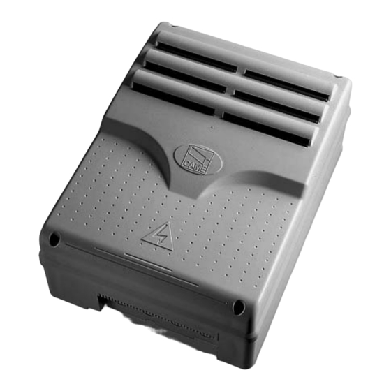
4.1 Dimensions
ZTC overall dimensions
240
240
4.2 Main components
1.
Dip-switch selecting features
2.
Control panel fuse 630mA F
3.
Accessories fuse 2 A F
4.
Line fuse 8 A F
5.
AF radio frequency card socket
6.
Power supply LED-signal light
4
Warning! Before acting on the device, cut off the main power supply.
Just operate the safety block on the ZT6C.
240
240
9
6
ZT6C case overall dimensions
240
240
7.
Radio code notifi cation LED light
8.
Connecting terminals
9.
Transformer connection terminals
10. Buttons to memorise radio code
11. Trimmer TCA: adjusting automatic closing time
12. PART. OPEN TRIMMER.: adjusting open-partially
3
2
165
165
11
12
7
1
5
10
8