CAME 9T90EN Instrukcja instalacji - Strona 4
Przeglądaj online lub pobierz pdf Instrukcja instalacji dla Panel sterowania CAME 9T90EN. CAME 9T90EN 12 stron. Control panel for 230 v - 400 v gearmotors
5 Installation
5.1 Preliminary checks
Before beginning to install, the following is necessary:
• Make sure that the point where the electrical panel is anchored is free from any impacts, and that the surface is solid and that
proper tools and materials are used (i.e. screws, wall plugs, etc.).
• Set up a suitable omni polar cut-off device, with distances greater than 3 mm between contacts, with sectioned power source.
•
Check that any connections inside the container (made for continuity purposes of the protective circuit) are fitted with extra
insulation compared to other internal conductive parts.
• Set up proper conduits and electric cable raceways, making sure these are protected from any mechanical damage.
5.2 Tools and equipment
Make sure you have all the tools and materials needed to carry
out the installation in total safety and in accordance with current
regulations. Here are some examples.
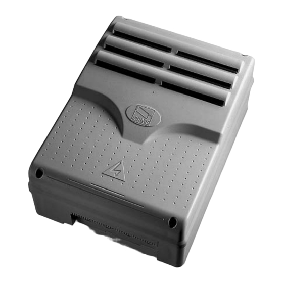
5.3 Fastening and mounting the container
1) Secure the base of the panel in a safe area; yes max. 6 mm
Head with to.
Assemble the pressure hinges.
5) Snap the cover onto the hinges.
2) Perforate the pre-punched holes and insert the cable glands
with corrugated tubes for the electrical cables to run through.
N.B.: the pre-punched holes have 20
mm diameter.
Careful not to damage the electronic
board inside the panel!
4) insert the hinges into the housing (either left or right) and secure
them using the issued screws and washers.
the slide to rotate
6) After adjusting and setting, secure the cover using the issued
screws.
15 mm ~