Consolidated VYNIL-VAC ASP-1105 Руководство - Страница 3
Просмотреть онлайн или скачать pdf Руководство для Водяной насос Consolidated VYNIL-VAC ASP-1105. Consolidated VYNIL-VAC ASP-1105 6 страниц.
INTRODUCTION & PERFORMANCE
Your Vinyl-Vac System has gone through extensive testing. Our goal is to move large amounts of air in order to handle almost any amount of
leakage through walls etc. creating a proper amount of suction and maintaining it.
For example, we have set liners with 6 foot inwall steps not covered, coping not taped, skimmers and returns not taped, and still set the liner
with no problem and cut in the steps dry. Even so, the more you seal off the pool from leaks, the better the suction and the more efficient the
Vinyl-Vac System will perform.
Your Vinyl-Vac System is specifically designed to move air at the source. Do not use as a water pump.
Caution: The blower housing contains a high speed fan blade that can amputate fingers. DO NOT OPERATE WITHOUT ALL PARTS IN
PLACE.
Your Vinyl-Vac System is designed for COMMERCIAL USE ONLY.
Your Vinyl-Vac System is wired at the factory for 120V operation. Connect to a 120V, 15 Amp. branch circuit and use a 15 Amp. time delay fuse
or circuit breaker. Your Vinyl-Vac System must be properly grounded. If not properly grounded, your Vinyl-Vac System can cause electrical
shock.
• Replace worn or damaged power cord immediately before using again.
• We suggest installing an inline GFI for safety and liability.
• Do not force the Vinyl-Vac System or attachments to do a job for which it was not intended or designed to do.
• Safety is a combination of common sense, staying alert and knowing how your Vinyl-Vac System works.
STEP TO FOLLOW BEFORE EVERY USE OF THIS VINYL-VAC SYSTEM
Check cap screw #523 (Refer to parts diagram in this manual) to make sure it is tight before each use. This cap screw secures the fan in place.
Note: The cap screw #523 has a left handed thread.
It is recommended to inspect your Vinyl-Vac System before each use. If any parts are missing, bent, fail in any way, or any electrical components
do not work properly, remove the power cord from the power source. Replace damaged or failed parts before using the Vinyl-Vac System again.
ASSEMBLY
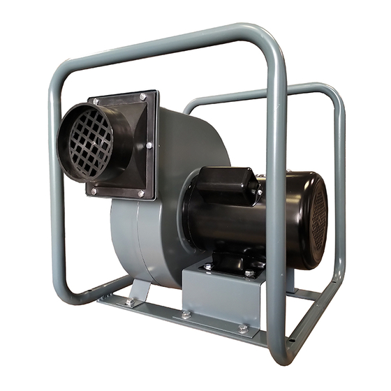
Your Vinyl-Vac System is almost completely assembled out of the box. Remove the
main machine and components from the box. Install the plastic outlet fitting (A) Fig.4
to the machine as shown using 6 hex. bolts, washers and hex. nuts (B). Install 4
rubber feet (diagram #510) to the bottom of the tube frame.
Your Vinyl-Vac System is now ready to operate.
OPERATION
Install a 4" tube (not included) to the machine inlet (diagram #521), do not glue these
parts together. Secure with clamp (not included) or screw provided.
Place 4" tube behind liner and tape to seal off air leaks. Tube should be lowered to
1" off the pool floor with angled opening facing the pool wall.
We suggest that the tube be placed 2 feet past breakoff for best results, see drawing
in Fig.5. This doesn't work with every liner installation, about 90% of the time it does,
kidneys are usually the exception. You sometimes have to find your own place,
depending on the fit of the liner.
Introduction, Assembly & Operation
FIGURE 4
FIGURE 5