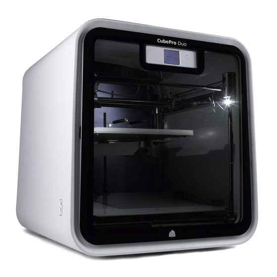
3D Systems CubePro Оригинальное руководство по эксплуатации - Страница 13
Просмотреть онлайн или скачать pdf Оригинальное руководство по эксплуатации для 3D-принтеры 3D Systems CubePro. 3D Systems CubePro 18 страниц. Unjamming extruder
Также для 3D Systems CubePro: Руководство (11 страниц), Оригинальное руководство по эксплуатации (12 страниц)

16. Insert both (2) 2.5 mm hex head screws through the cartridge sensor
and cartridge sensor shim. Secure the screws through the inner floor,
to the cartridge bay.
CAUTION: Do not over-tighten the screws. Over-tightening
the screws could damage the cartridge sensor and void the
manufacturer's warranty.
NOTE: Proceed to step 21 if no other parts are being
replaced.
17. To replace cartridge bay 2 PCB, loosen and remove both 2.5 mm hex
head screws securing the cartridge bay sensor assembly to cartridge
bay 2.
NOTE: To install cartridge bay 2 PCB, proceed to step 20.
18. To replace cartridge bay 2, loosen and remove the four (4) 2.5 mm hex
head cap screws (A) and 7 mm nuts (B) securing the lower hinge of
cartridge 2 to the inner floor.
3D Systems, Inc.
12
Bottom of Inner Floor
A
B
