Autonics ADS-SE1/2 Manuel - Sayfa 3
Aksesuarlar Autonics ADS-SE1/2 için çevrimiçi göz atın veya pdf Manuel indirin. Autonics ADS-SE1/2 6 sayfaları. Door side sensor

ADS-SE1/2
Installation
Controller
1. Follow as below when adjusting wiring length.
Cut off the wiring length as much as user needs.
Connect the wire to the terminal after taking off the wire
covering. It is easy to connect if soldering the end of the
wires.
※ Be sure of connecting wires in power off.
※ Follow the figure when cutting off the wires of sensor
head. If the cover of wire is taken off too much, it may
cause damage to this product as the end of both wires is
shorted.
17mm
2. Match wires in the number of terminals and connect
them.
Do not connect extended wire to the wire of sensor head.
It may cause malfunction by noise.
Do not connect two wires or more to a terminal.
Output (N.O.) (N.C.)
Power
(12-24VAC/VDC)
Output (N.O.) (N.C.)
Power
(12-24VAC/VDC)
C-18
Outer shield wire
Inner covered wire
9mm
<1-channel>
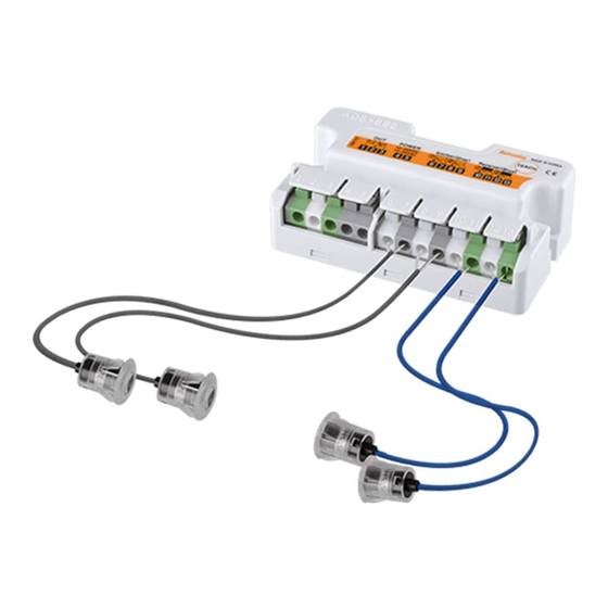
Emitter
Receiver
(gray)
(blue)
<2-channel>
①
②
①
②
Emitter
Receiver
(gray)
(blue)
Connection method for power and output wires
• Press a connecting button and wiring it.
• It does not operate normally if the wiring is connected
conversely.
• Make sure of connecting power wire to the terminal 4,
and 5. Otherwise, It may cause damage to this product.
• Allowable diameter of power and output wires
-Single and Stranded wire: 0.2 to 1.5 mm
Caution for installing controller
Fix a controller with 2 fixing bolts.
Process the fixing holes of a controller by M4.
Refer to "
Dimension" for the position of holes.
Do not tighten bolts to fix a controller. The fixing holes of
controller may be broken.
Sensor
1. Make a hole on the side post of auto door as
follows.
When not using the mounting bracket
① One push method
• Mounting hole for sensor head:
• Panel thickness for sensor head: 1.5
② Screw method
• Mounting hole for sensor head: M10×0.75mm
• Panel thickness for sensor head: 1.5
When using the mounting bracket
① One push method
• Through hole for sensor head:
• Fixing screw hole for bracket: M4 Tap or Ø3.5mm
② Screw method
• Through hole for sensor head:
• Fixing screw hole for bracket: M4 Tap or Ø3.5mm
※ Check the mounting holes for the head of emitter and
receiver are in parallel for the optical axes.
※ Grind around the mounting holes drilled smoothly.
It may hurt by sharp parts and cause malfunction by the
inclined sensor head.
2
±0.1
12.2
mm
Ø
±0.5
mm
±0.5
mm
13 to 14mm
Ø
13 to 14mm
Ø
