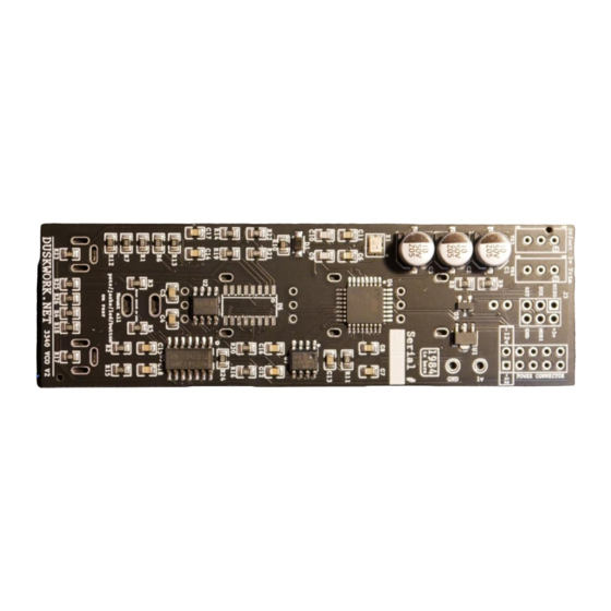
DUSKWORK VCO V2 Manuale di costruzione - Pagina 3
Sfoglia online o scarica il pdf Manuale di costruzione per Unità di controllo DUSKWORK VCO V2. DUSKWORK VCO V2 7.

| DUSKWORK.NET | Self-Tuning VCO V2 Build Guide
Step 3: Next, you'll need to add 1 x 300KΩ 1/4w resistor between pins 15 + 16 of the AS3340
IC. It's important that this doesn't short anywhere else on the PCB or other components. The
best way to do this is to bend one leg against the body of the resistor to reduce the size of its
footprint. See photos below for to visualise how it should sit.
Before
After
Step 4: Now it's time to start soldering the through hole components. Start with the 2 x 10K
trim pots at the top of the board. One is to adjust the 1v reference signal, the other is to
adjust the 1v/oct CV tracking
5
3
