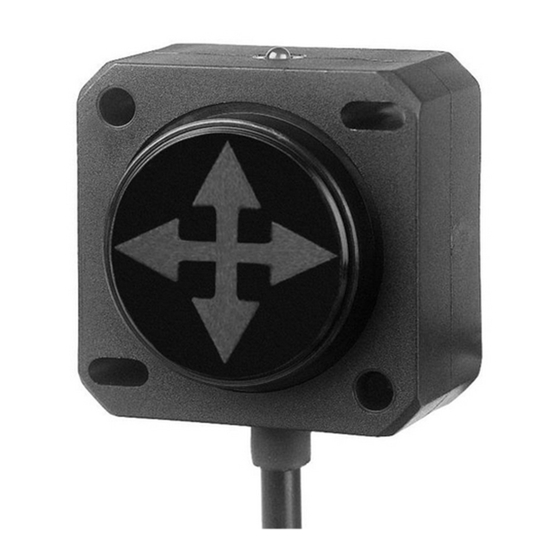
DIS Sensors QG40N Manuale d'uso - Pagina 13
Sfoglia online o scarica il pdf Manuale d'uso per Interruttore DIS Sensors QG40N. DIS Sensors QG40N 15. Tilt/acceleration switch (sil1 plc)
Anche per DIS Sensors QG40N: Manuale d'uso (5 pagine), Manuale d'uso e sicurezza (6 pagine)

Mounting
Figure 8 - Horizontal mounting 2-axis
• The sensor should be mounted on a stable flat surface with at least two screws tightened.
• Never move the sensor by pulling the cable.
• A 1-axis tilt switch must be mounted vertically. The factory default zero position is with the
male connector pointing down as shown in Figure 3. The sensor can be zero adjusted at any
position within the full range.
• A 2-axis tilt switch must be mounted horizontally. The factory default zero position is shown
in Figure 2. After installation, the sensor can be zero adjusted to eliminate the mechanical
offsets within a ±5° offset range.
DIS SENSORS BV
User Manual - QG40N Tilt/Acceleration Switch (SIL1 PLc) V2.0
Figure 7 - Mechanical drawing of QG40N with a male M12
Figure 9 Vertical mounting 1-axis
12
