HP ProCurve 1600M Kurulum Kılavuzu - Sayfa 5

Anahtar HP ProCurve 1600M için çevrimiçi göz atın veya pdf Kurulum Kılavuzu indirin. HP ProCurve 1600M 12 sayfaları. Redundant power supply
Ayrıca HP ProCurve 1600M için: Şartname Sayfası (12 sayfalar), Önce Beni Oku (8 sayfalar), İnceleme El Kitabı (27 sayfalar), Tamamlayıcı Kılavuz (2 sayfalar), Tamamlayıcı Kılavuz (2 sayfalar), Kurulum Kılavuzu (28 sayfalar), Kurulum Kılavuzu (36 sayfalar), Kurulum Kılavuzu (28 sayfalar), Hızlı Kurulum Kılavuzu (2 sayfalar), Hızlı Kurulum Kılavuzu (4 sayfalar), Kullanıcı Kılavuzu (8 sayfalar), Kılavuz Eki (28 sayfalar), Önce Beni Oku (16 sayfalar), Kurulum ve Sökme (2 sayfalar), Planlama ve Uygulama Kılavuzu (40 sayfalar), Ürün Kullanım Ömrü Sonu Sökme Talimatları (2 sayfalar), Kurulum Kılavuzu (46 sayfalar), Teşhis Kılavuzu (2 sayfalar), Sökme Talimatları (2 sayfalar)
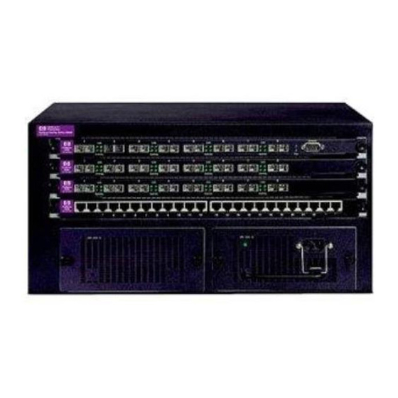
HP ProCurve 1600M Kurulum Kılavuzu
Fan Tray Installation Steps
Follow these steps to install the replacement fan tray into the back of the Switch 4000M
or 8000M:
1. Disconnect AC power and remove power supplies and back cover plates.
On the back of the switch, dis-
connect all AC power. Then,
loosen the 4 screws holding in
each power supply or cover
plate, and remove the power
supplies and cover plates
2. Mark and disconnect the network cables on modules in slots A and B.
On the front of the switch, mark or otherwise note the location of the network
cables attached to the network modules in switch slots A and B so that you can
reconnect the cables to the correct ports at the end of this procedure. Then,
disconnect all network cables from modules that are installed in slots A and B
on the front of the switch.
Alternatively, if you have sufficient slack in the cables, you can leave the network
cables connected to the modules as you complete the next step.
3. Remove the Management module and any modules that you have
installed in slots A and B.
Loosen the two screws holding
in each module, and use the
screws to slide the modules
out. Remember which module
is located in which slot.
Caution: When handling the mod-
ules, do not touch the components
on the module boards or the edge
connectors. Otherwise, damage
due to static discharge could
occur.
5