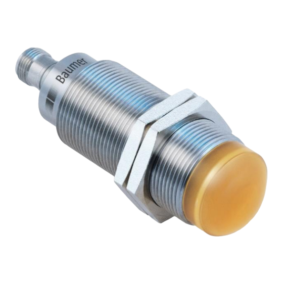
Baumer IO-Link RR30 Інструкція з експлуатації - Сторінка 2
Переглянути онлайн або завантажити pdf Інструкція з експлуатації для Аксесуари Baumer IO-Link RR30. Baumer IO-Link RR30 40 сторінок. Radar sensor

Instruction Manual for Radar Sensor RR30 with IO-Link
Content
1
Sensors covered by this manual ................................................................................................ 4
2
IO-Link Introduction ..................................................................................................................... 4
2.1
SIO / DI Mode ................................................................................................................................. 5
2.2
IO-Link Communication Mode ........................................................................................................ 5
2.2.1
Cyclic data ...................................................................................................................................... 5
2.2.2
Acyclic data ..................................................................................................................................... 5
2.3
IO-Link Device Description (IODD)................................................................................................. 5
2.4
Off-Line Parametrization ................................................................................................................. 6
3
Sensor in the IO-Link Communication Mode ............................................................................. 7
3.1
Signal Path ..................................................................................................................................... 7
3.2
Process Data .................................................................................................................................. 8
3.2.1
Process Data-In .............................................................................................................................. 8
3.2.2
Process Data-Out ........................................................................................................................... 9
4
Parameter .................................................................................................................................... 10
4.1
System Commands ...................................................................................................................... 10
4.2
Measurement Data Channel (MDC) ............................................................................................. 10
4.2.1
Measurement Value Distance ....................................................................................................... 10
4.2.2
Switch Counts ............................................................................................................................... 10
4.2.3
MDC Source ................................................................................................................................. 11
4.2.4
MDC Unit Code............................................................................................................................. 11
4.2.5
MDC Setpoint limit ........................................................................................................................ 11
4.3
Switching Signal Channel (SSC) .................................................................................................. 12
4.3.1
Setpoint SP ................................................................................................................................... 12
4.3.2
SSC Configuration ........................................................................................................................ 13
4.3.3
Channel Logic ............................................................................................................................... 13
4.3.4
Switching Mode ............................................................................................................................ 13
4.3.5
Hysteresis Alignment Mode .......................................................................................................... 14
4.3.6
Hysteresis Width ........................................................................................................................... 15
4.3.7
Time filter ...................................................................................................................................... 15
4.3.8
Counter / SSC4............................................................................................................................. 18
4.4
Teach Channel Selection & Teach Status..................................................................................... 20
4.5
Static ............................................................................................................................................. 21
4.6
Signal Processing ......................................................................................................................... 21
4.6.1
Process Value Exponential ........................................................................................................... 21
4.6.2
Disruption Filter............................................................................................................................. 22
4.6.3
Region of Interest ......................................................................................................................... 22
4.7
Expert settings .............................................................................................................................. 23
4.7.1
Measurement Sensitivity Scale .................................................................................................... 24
4.7.2
Peak Selection Mode .................................................................................................................... 25
4.7.3
Operation Modes - Measurement Modes ..................................................................................... 27
4.7.4
Process Value Exponential Filter. Peak Filter ............................................................................... 27
4.7.5
Object Tracking Mode ................................................................................................................... 27
4.7.6
Object Tracking Hold Time ........................................................................................................... 28
4.8
Output Settings ............................................................................................................................. 28
4.8.1
Switching Output........................................................................................................................... 28
4.8.2
Analog Output ............................................................................................................................... 28
en_BA_RR30_IO-Link_V0.23.docx
13.01.2021/
2/40
Baumer Electric AG
Frauenfeld, Switzerland
